Sevak Engineers / Dimensional Inspection
CAD-to-Scan Comparison
Precision Inspection. Clear Insights. Better Quality Control.
We provide CAD-to-scan comparison services to evaluate manufactured components against their original CAD models. By aligning 3D scan data with the reference design, we identify dimensional deviations and visualize variations through colour deviation maps. This allows engineers to quickly identify areas that differ from the intended geometry, assess manufacturing accuracy, and support quality control and process improvement.
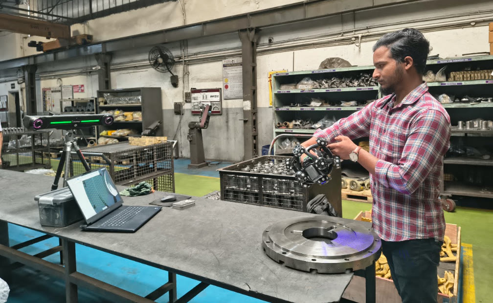
Our process
From reference design to visible deviations
Illustrative schematic — not customer inspection results
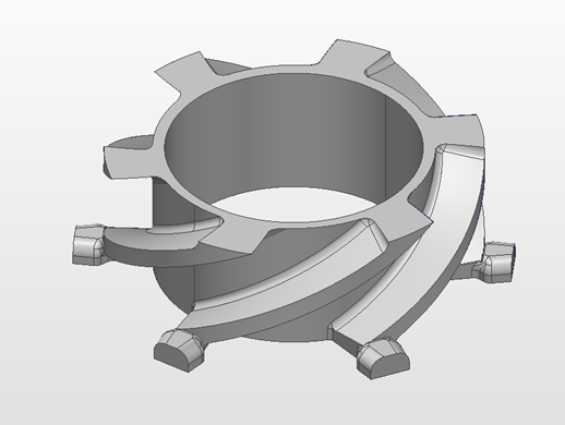
Reference CAD Model
The nominal CAD model used as the design reference.
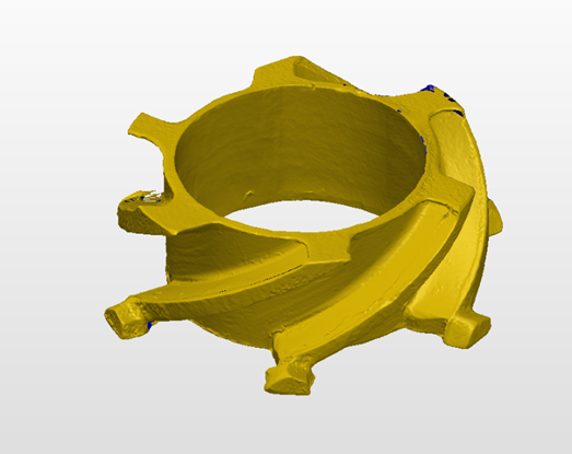
Aligned 3D Scan
The 3D scan of the manufactured part, aligned to the CAD model.
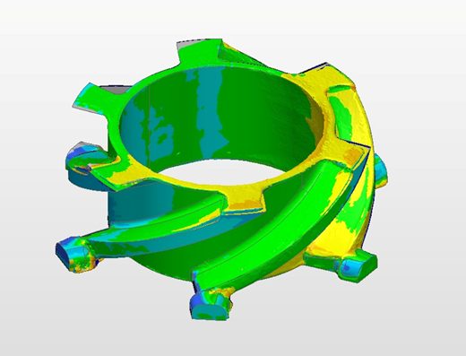
Colour Deviation Map
A colour map showing where the part deviates from the design.
Green indicates areas within tolerance. Yellow, red and blue indicate positive or negative deviation from the CAD model.
Our Capabilities
3D Scan-to-CAD Alignment
Align scanned component data with the original CAD model to establish a reference for accurate geometric comparison.
Colour Deviation Mapping
Visualize dimensional variations using colour-coded deviation maps that highlight areas where the manufactured component differs from the reference design.
Dimensional Deviation Analysis
Identify geometric differences between the scanned component and the CAD model to support dimensional evaluation and inspection.
Manufacturing Quality Verification
Evaluate whether manufactured components conform to the intended design and specified tolerances, based on the available inspection criteria.
Inspection Reporting
Present visual comparison results and inspection reports to help engineers understand deviations and support corrective actions.
How It Works
Scan the Component
Capture the physical geometry of the manufactured component using 3D scanning equipment.
Align the Data
Align the scan data with the reference CAD model using the appropriate inspection workflow.
Analyse Deviations
Compare the two datasets and visualize geometric differences through a colour deviation map.
Review the Results
Use the comparison results to identify areas requiring further inspection or corrective action.
Applications Across Industries
Why Choose Sevak Engineers?
Clear Visual Results
Colour deviation maps make geometric differences easier to understand.
Design Verification
Compare actual component geometry against the intended CAD design.
Quality Control Support
Identify areas requiring further investigation or corrective action.
Engineering Insights
Support manufacturing decisions with detailed digital comparison data.
Is Your Manufactured Component Matching the Original Design?
Let our engineering team help you evaluate dimensional deviations and understand component geometry.
Ask about this service