Sevak Engineers / 2D Profile Generation
2D Profile Generation
From 3D Scan Data to Precise 2D Drawings.
We convert 3D scanned data into dimensioned 2D engineering drawings to support laser cutting, sheet metal fabrication, and bending operations. By extracting relevant profiles and geometric information from scanned components, we help create clear digital drawing references for manufacturing. Our approach supports the preparation of component outlines, dimensions, and fabrication details according to project requirements.
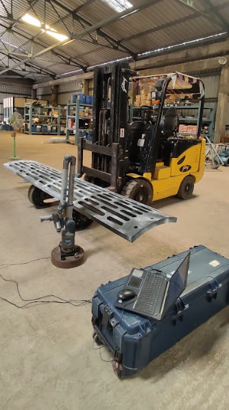
Our process
From 3D Scan Data to Manufacturing Drawings
Illustrative workflow — final drawing requirements depend on the component and manufacturing process.
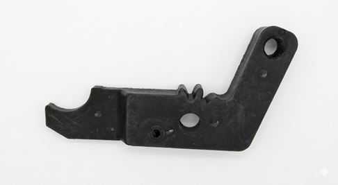
3D Scanned Component
Begin with scanned component data that provides a digital reference for understanding the physical geometry.
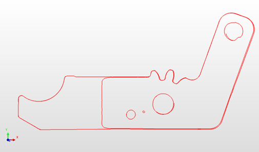
2D Profile Extraction
Identify the required component outlines and geometric features to develop the appropriate 2D profile.
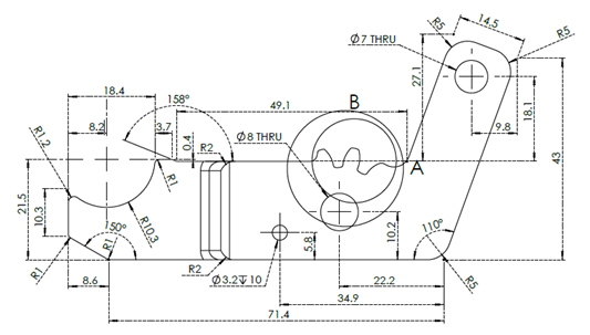
Dimensioned 2D Drawing
Prepare a clear, dimensioned 2D drawing for relevant laser cutting, sheet metal fabrication, and bending workflows.
Our Capabilities
2D Profile Extraction
Extract relevant two-dimensional outlines and geometric profiles from available 3D scan data to support drawing preparation.
Dimensioned Engineering Drawings
Prepare 2D drawings with relevant dimensions and geometric details according to the component and project requirements.
Laser Cutting Profiles
Prepare suitable 2D profile drawing references for laser cutting applications, subject to the requirements of the manufacturing process.
Sheet Metal Bending Support
Support sheet metal fabrication by preparing drawing references for relevant profiles and bending requirements.
Manufacturing Drawing Preparation
Organise component geometry and drawing information into clear digital references to support downstream fabrication workflows.
How It Works
Review the Scan Data
Review the available 3D scan data and identify the component geometry required for the drawing.
Extract the 2D Profile
Derive the required outlines and geometric features from the available component data.
Prepare the Drawing
Develop the 2D engineering drawing with relevant dimensions and details based on the project requirements.
Review for Manufacturing
Review the drawing against the agreed requirements before using it as a reference for laser cutting, bending, or fabrication.
Applications Across Industries
Why Choose Sevak Engineers?
Scan-Referenced Drawing Preparation
Use available 3D scan data as a reference for developing relevant 2D component profiles.
Dimension-Focused Outputs
Prepare drawings with the dimensions and geometric information required for the intended application.
Fabrication-Oriented Support
Support drawing preparation for laser cutting, sheet metal bending, and related fabrication workflows.
Clear Engineering References
Organise component outlines and drawing details into a format that supports manufacturing communication.
Application-Specific Approach
Adapt drawing preparation to the component geometry, available scan data, and agreed manufacturing requirements.
Need 2D Profiles for Your Manufacturing Requirements?
Talk to Sevak Engineers about converting your 3D scan data into dimensioned 2D drawings for laser cutting, bending, and fabrication applications.
Ask about this service